First, note that this guide is for the Warsensor WS66 and Miltec MT66 but is also somewhat useful for the Armotech WS65 and Miltec MT65. They share many parts and the differences should be apparent. Note that if you are familiar with Spyder style stacked tube blowback markers most of these instructions will be very familiar to you.
For reference, here is the official users manual for the WS66 from www.armotech.co.uk. Anytime the instructions differ from my guide I'd suggest following the manufacturer's instructions and e-mail me about the conflict. I have tried to make this breakdown as detailed as possible while incorporating the manufacturer's instructions into the guide but hey, no one is perfect.
|
 |
Okay, so this is what we are starting with, the Warsensor WS66. This one is the Elite model. Hey, their name, not mine, but this is my personal marker. Note that the regulator under the handle is not stock nor is the three point sling but other than that this is how I got the gun from Warsensor.
IMPORTANT NOTE: ALWAYS make sure the marker is unloaded and un-aired before performing any work! |
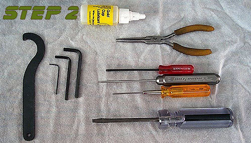 |
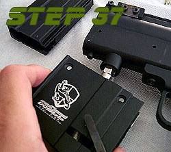
Doesn't seem like a "step" but believe me, getting your tools together so you have everything you need at hand makes life easier. The WS66 really only requires a set of allen wrenches but here we see some tools to make life easeir. The needle nose pliers and screwdriver make a couple steps simpler while the quality allen drivers in 2.0mm, 2.5mm and 3.0mm keep us from stripping screws heads. The big "hook" looking tool on the far left came with the marker and is a special tool for removing the CAR stock that comes with the WS66. |
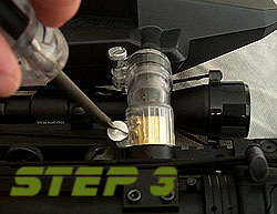 |
I'd like to think that this is a no brainer but if not, start your disassembly by taking off the hopper at the lower elbow clamp. Sometimes I tighten mine down very tight to keep them from coming off during a game so you may need to use a screwdriver to loosen them like I do. Plus there isn't a lot of room with the scope and all so this makes it a bit easer to get to the mounting screw anyway. |
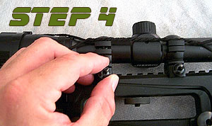 |
Next let's get that scope out of the way. Now, it's optional to remove the scope as, when you remove the handle (as is shown in steps 8 and 9) the scope will go with it. However, this is a very comprehensive teardown so we're showing you almost everything. Loosen the tow thumb screws that hold the scope rings to the handle rail. Use a screwdriver if necessary. |
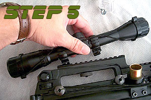 |
Once you have loosened both nuts (I've removed them here as these rings were really tight on the rail and needed them fully removed) you can then remove the scope and rings from the rail. |
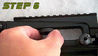 |
Like with the scope the Elite Rail can remain on the handle but you can remove it for cleaning or to change attachments. Remove the thumb nut that is under the top handle. Be careful as there is a small washer between this nut and the handle itself. Note that while this is for the WS/MT66 marker, any M-16/M-4 carry handle sight mount will work in this fasion. |
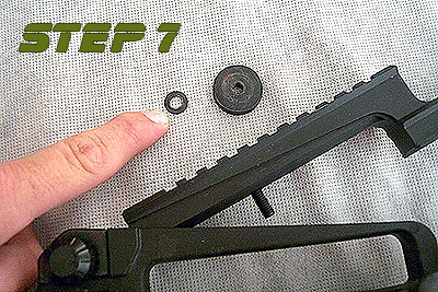 |
Here is that washer mentioned in step 6. Be sure not to lose this. Once this is off the Elite Rail will slide up and out of the recess in the top handle. I usually then put the washer and thumb nut back on the stud in the rail after removing it to prevent me from losing them. |
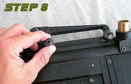 |
The Carry Handle is held on just like the Scope Rings. Loosen these thumb screws by hand or you can use a flathead screwdriver if they are on very tight. As always, be careful not to strip the slots if you use a screwdriver. |
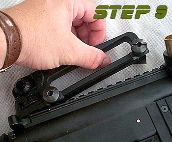 |
Once both thumb screws are loose the handle will lift off the top of the receiver. Again, leave the thumb screws on the studs in the carry handle to prevent them from getting lost. |
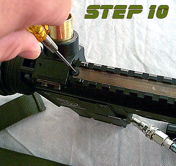 |
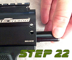
Now we're going to start getting to the internals. First we need to remove the brass cover plate that is on top of the upper receiver and was covered by the carry handle. First, remove the flathead screw that is located towards the front of the marker using a 2.0mm allen wrench or, as in the picture, allen driver. It should not be in very tight as overtightening this screw will press the brass cover down into the charging handle that rests underneath and will make it difficult to cock the marker. (In other words, make a note of this for when you need to reassemble the marker!!!!) |
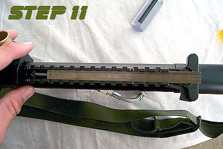 |
Once the screw is out the brass plate will slide out the rear of the receiver. It is usally helpfull if you pull the charging handle out a little bit to get the thin brass plate to clear. |
 |
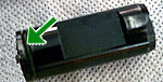
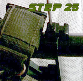
Now the charging handle will lift out of the upper receiver. Be carefull to lift the spring at the front of the lever off the screw in the receiver that it attaches to (white arrow in picture). It will lift off the screw easily. |
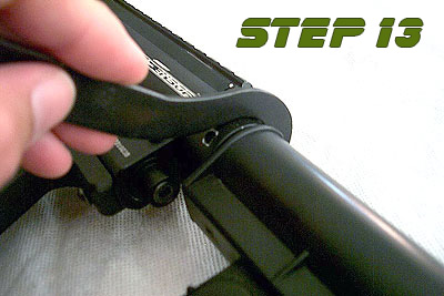 |
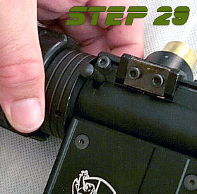
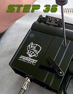
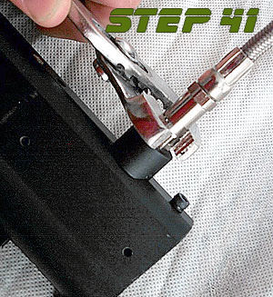
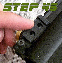
Next we get to use that special tool we talked about earlier. It's call a stock wrench. On the open end of the "hook" you'll see a little nub. This nub goes in one of the holes on the stock nut like you see in the picture on the left. Positioning the wrench as show in the picture will allow you to loosen the nut. Positioning it with the handle facing to the right of the marker (when placed on the top of the nut and looking at it from above) will tighten the nut. This is another little "Keep for putting the marker back together later" kind of note. |
 |
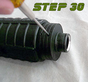
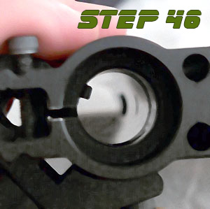
Once the Stock Nut is loosened, you can remove the upper strip pin that holds the stock in place. Be careful to loosen the UPPER pin as the lower pin is holding the striker spring in place and is under pressure. When Reassmebling the marker it is important to note that the stock can go back into the marker at ANY angle. Thus, to reassemble put the stock back in the marker, insert the strip pin, alight the stock so that it is in line with the receiver, then tighten the stock nut. If after tightening the stock isn't straight, loosen the stock nut a little, realign the stock, and retighten while holding the stock securly to keep it from turning while tightening. If the stock doesn't slide in or out easily this is normal. Wiggle it a bit and it should come out or go in...depending on what you're doing. |
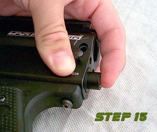 |
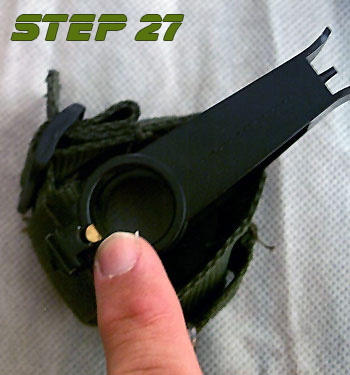
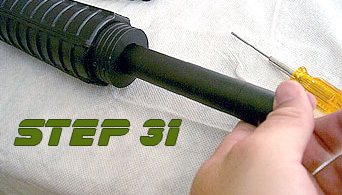
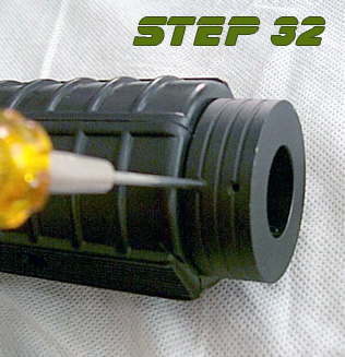
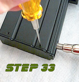
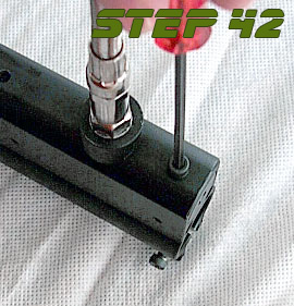
Now we're taking off the velocity cap. The velocity adjustment screw is in this cap but doesn't ever need to be removed unless you are replacing it...and why you would need to replace it is beyond me. Thus we leave it in. To remove the rear cap, hold the receiver as shown in the picture with your index finger pressing in on the velocity cap. This releases pressure on the strip pin. While holding the cap in this manner, use another finger to push the strip pin out. Remove the strip pin with your free hand. Then, gently release pressure on the velocity cap. The velocity spring inside the receiver will push on the cap and if you just release it parts will fly everywhere. So slowly release pressure on the cap until the spring is fully relaxed. |
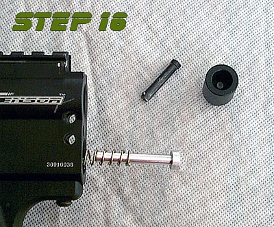 |
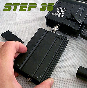
If you've done it right you should have something that looks like the picture on the left. The cap and strip pin are out and the velocity spring and spring guide are hanging out the back of the marker like this. Remove the spring and guide laying them asside...preferably somewhere they won't get lost. |
 |
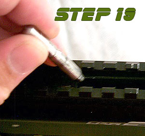
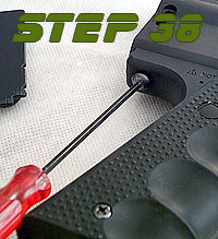
Now you need to remove the rubber striker bumper that is in the lower tube of the receiver. I have found it helpful to use a small allen driver (2.0mm shown here) to remove this rubber piece. Just be careful NOT to let the tip of the tool you use scratch the inside of the lower tube. |
 |
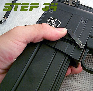
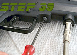
Now we need to remove the link pin that connects the bolt in the top tube to the striker in the bottom tube. I've found it is easier to slide this pin as far back as possible to make it easier to remove the striker. Also, using needle nose pliers helps remove this pin. |
 |
Once you have this pin out be carefull as the bolt is now able to slide back and forth freely in the upper tube. |
|
By tilting the receiver back, you can slide the bolt out easily as seen here. Remove the bolt at this time. |
 |
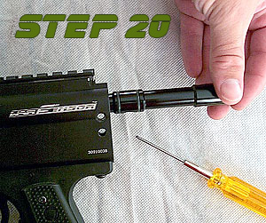
Now for the striker. If you move the link pin back as far as it would go in step 18, you can skip the first part of this.Using an allen wrench or driver, you'll need to move the striker back using the hole for the link pin located towards the back of the striker. Once this is done, or if you did it in step 18, you next want to place the tip of the tool on the face of the striker and push it out towards the back of the receiver until it potrudes from the lower tube as seen on in the picture at left. |
 |
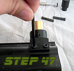
Now remove the striker from the lower tube. Note that if you remove the trigger assembly before you do all this the striker will just slide out but we are writing this guide not just for disassembly but for cleaning the marker as well removing the trigger is not necessary for cleaning. |
 |
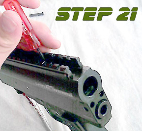
And speaking of cleaning, this is a good time to talk about oiling your internals and how the bolt goes back in the marker. First, you want to wipe down your bolt and striker with a soft, damp cloth making sure to get all paint residue off the bolt (there shouldn't be any on the stiker but you never know). Next, you want to oil all the o-rings on both the striker and the bolt. The bolt has 4 and the striker has one (marked by the green arrows in the pictures to left). The front of the bolt is where the first o-ring is (in the upper right of the picture). Place the bolt in the upper tube this end first. Also note the large hole in the bottom of the bolt between the two last o-rings. This hole MUST face down in the receiver for the marker to work. |
 |
The striker goes in the bottom tube o-ring end first and the flat spot on the bottom of the striker (seen in the picture just behind the green arrow) must face down. To get the striker in the marker, push it into the bottom tube. It will stop before it gets all the way in (it is being stopped by the trigger sear). To push it in further, first take the safety off. Then press firmly on the back of the striker. While pressing on the striker, pull the trigger. This will drop the sear and allow the striker to enter the lower tube. Keep in mind that the striker is now in the "cocked" position. After re-installing the bolt, link pin, and the velocity spring you will need to peform this action once again (this time while pushing on the velocity spring) to "un-cock" the marker and continue reassembly. |
| If you are just disassembling your marker for routine maintainance, this is as far as you need to go. The rest of this is only if you need to disassemble the marker for a thourough cleaning after a hard day of play and, like me, want to get every last drop of paint off the marker. The only part of the marker we will not disassemble will be the volumizer section and valve body but we will mention how far you need to disassemble the marker to perform these tasks. |
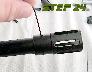 |
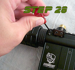
Now we move on to removing the barrel. First, remove the muzzle break. It is held on to the barrel with one set screw. Using a 0.5mm allen wrench, loosen the screw but do not remove it from the muzzle break as it is very small and easy to lose. Also, when reassembling, be careful not to over tighten this screw as doing so can damage the barrel. I've seen people DENT the INSIDE of their barrel by over tightening these screws. Also, on reassembly it is a good idea to remove this screw and apply a small amount of blue locktite before reinstalling it to prevent it from loosening up while playing. |
 |
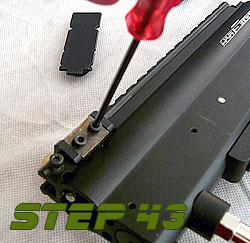
Next you need to remove the front sight and front handgard plate. The two are attached to one another by a single screw. You do not need to remove this screw because the two pieces can come off still attached to one another. Just loosen the set screw that is on the bottom of the front sight. It is located towards the front of the sight and is a 1.0mm screw. |
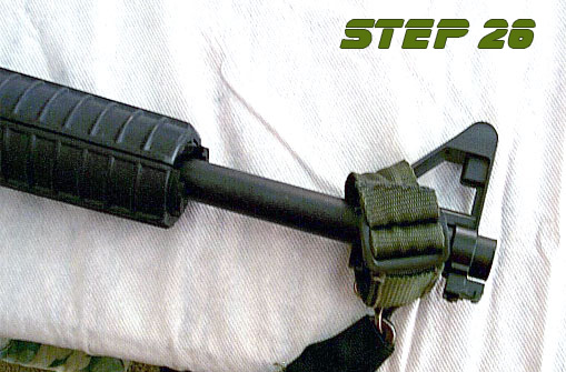 |
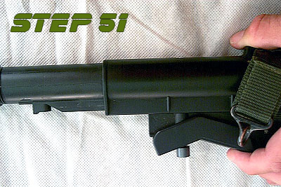
The front sight and front handgard plate (obscured by the tactical sling in this picture...but as you can see it can come off while attached to the sight) now will slide off the front of the barrel. |
 |
Be careful of this brass bushing though. It is small and located in the front sight just above the set screw. The set screw pushes against this bushing which then presses against the barrel. It's there to prevent damage to the barrel when the screw is tightened. With the sight off the barrel, this piece can fall out VERY EASILY. Thus keep it someplace secure so that you do not lose it. |
 |
Next we'll remove the barrel from the receiver. First, loosen the 3.0mm cap head screw that clamps the barrel in the upper receiver tube. You do not need to remove this screw completely, just enough to allow the barrel to loosen up. |
 |
Once the barrel screw has been loosened, remove the barrel pin that is located just under the barrel screw. The barrel will now slide of out the receiver. If it doesn't, loosen up the barrel screw a bit more until it does. When re-attaching your barrel, be sure to put the pin in first then tighten the barrel screw.
|
 |
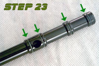
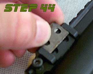
IMPORTANT NOTE: On some Warsensor barrels the three "hop up" groves were not machined in the correct location in relation to the mark for the barrel pin. These grooves should be at the 11, 12, and 1 o'clock positions. (like picture on left.) If they do not line up this way when the pin is installed, remove the pin, line the grooves up correctly, and tighten the barrel screw to hold the barrel in place. It will not harm the marker or barrel by not using the barrel pin. |
 |
Next is the handgaurd on the barrel. Note that on each side of the barrel at the 8 and 4 O'Clock positions are two 1.0 mm set screws. Loosen the two that are closest to the back of the barrel as seen in the picture at left. Do not remove them completely. On re-assembly, apply a bit of blue lock-tite to them and do not over tighten as they can damage the barrel. |
 |
Once loose, the barrel will slide out of the handgaurd. When reassembling the marker, it is best to install the barrel to the receiver first making sure it is properly aligned and then installing the handgaurd. This way it is easier to position the handgaurd correctly. |
 |
To remove the rear handgaurd ring, loosen the front pair of set screws. Again, this is only necessary if you need to clean the inside of the handgaurd (it happens). Again, when reassembling it is best to put some blue lock-tite on these screws. Also, the handgaurd pictured is plastic so be careful when screwing these back in that you do not overtighten and crack the plastic. If you have the R.I.S. handgaurds (as I do now) it is aluminum and you can tighten these down a bit more. However, you still want to be careful as if you do tighten them to much you can strip the screws themselves. |
 |
To remove the magazine assembly, you'll first need to remove the bottom cover on the magazine itself. There are four 1.0mm set screws that hold this on, two on each side. Loosen these screws but do not remove them completely. Again, on reassembly it is best to apply a little bit of blue lock-tite to these screws. However, the bottom plate is plastic and lock-tite will eat plastic so be careful to apply only a small amount to the screw itself. Once the screws are loosened properly the bottom cover will just lift out of the magazine assembly. |
 |
Next you will need to remove the magazine from the magazine well. To do this, push the textured button on the right side of the magazine well to release the magazine lock lever. You can swivel the magazine lock lever up to hold it in place making the magazine removal easier. (Shown here.) |
 |
Now the magazine will slide out of the magazine well. Note the routing of the airline through the magazine for reassembly. |
 |
Now remove the four 2.0mm screws that are holding the magazine well to the receiver. There are two on each side. Again, during reassembly be sure to use a little bit of lock-tite on these screws to hold them in place. |
 |
The magazine well will come off the bottom of the receiver farily easily. Note the direction of the magazine well for reassembly. |
 |
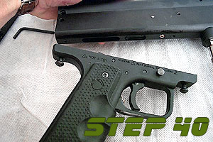
Next is the trigger assembly. Please note that you CANNOT remove the trigger assembly WITHOUT first removing the magazine assembly. To start removing the trigger, loosen the 3.0 mm button head screw at the rear of the assembly. This screw threads into both the trigger assembly and the receiver assembly thus you do not have to remove it entirely. |
 |
Next loosen the 3.0 mm screw at the front of the trigger assembly. You'll note that this screw is normally covered by the magazine well. Like the rear screw, you only need to loosen this screw enough to back it out of the receiver. |
 |
Here you can see the front and rear screws stay in the trigger assembly when it is removed from the receiver. Remember, with both trigger screws that they should have a little bit of blue lock-tite applied to them before reassembly. For the curious sort, the silver screw you see in the bottom of the receiver that was covered up by the trigger is the screw that holds in your valve assembly. Unless it's loose, don't touch it if you are not removing the valve body. |
 |
With that being said, if you do need to get into the volumizer section or replace the braided line into the marker for whatever reason, you first need to remove the magazine assembly. Once removed, you can remove your airline using a pair of pliers or an open end wrench. The wrench is a better option but at the time I did not have a proper fitting wrench so I had to use pliers. They can, and usually will, scratch the fitting so I advise against it if at all possible. |
 |
To remove the volumizer cap you must take out the 3.0 mm screw that is located at the front of the receiver on the bottom side just in front of the air fitting. Once removed you will then need to unscrew the volumizer cap from the receiver. There is an allen wrench fitting on it's face for this purpose but I cannot remember what size it is. Once the cap is out you can remove the volumizer spring, cup seal and valve pin. The only time you would need to do this is if you suspect you have a leak and need to replace the cup seal or if you need to service your valve. In the four years I've had my WS66 I've had to do this once. |
 |
One item that may need maintenance from time to time is the ball detent. Note that if you need to replace your detent it is the same detent used on the old VM-68 thus you should be able to find them that way. To adjust the detent, loosen the two 3.0 mm cap head screws that hold it in place and then move it up or down per your needs. Retighten these screws to set it in place. If you wish to remove it, then remove these two screws completely. |
 |
There is a metal cover over the detent to hold it in place once the screws are tightened. Remove this after you remove the two screws and set it aside. |
 |
Now the ball detent can be removed. Note how the holes in the detent are oblong for adjustability. |
 |
When reinstalling or setting the detent, it should look like this inside the upper receiver when viewed from the front. Note that the receiver is on it's side and the top of the receiver is pointed towards the left side of the picture. Do not overtighten the screws that hold the ball detent in place as doing so will warp the detent. Just tighten them snug. If they come loose, apply blue lock-tite to the holes in the feed neck and put the screws back in tightening them snuggly. |
 |
The feed neck is held onto the marker by two 4.0mm cap head screws. Remove these two screws completely. Be careful though not to lose the two washers that are under these screws. If you are just cleaning your marker you do not need to remove the detent from the feed neck. Also, you may want to check the 2.0mm set screw that holds the brass tube in the feed neck. If it keeps loosening, apply a small amount of blue lock-tite to it to keep it secure. |
 |
Once the screws are out the feed neck will lift off the receiver. |
 |
Remember those two small washers I mentioned? They usually stay in the feed neck when you remove it. Be careful not to lose these. |
 |
Sometimes people complained that their stock was loose and they couldn't figure out how to make it tight. They had tightened the stock nut as far as they could and the problem persisted. The reason this is so is because the plastic stock is actually secured to a metal tube inside the stock. To fix this, or if you wish to disassemble the stock for some reason, you first need to move the stock out to it's longest length. Depress the stock adjustment handle as seen in the picture at left... |
 |
...and while holding it down slide the stock as far out as you can get it. |
 |
Now turn the stock over so that you are looking at the bottom of the stock. You'll se up towards the front of the stock a small set screw in a small hole. This set screw is what holds the plastic stock secure on the inner metal tube. If your stock has become loose, remove this screw, clean it, apply a small amount of blue lock-tite, and reinstall it. I suggest doing this while the stock is on the marker so that you can align it properly. If you are disassembling the stock, loosen this screw but be sure to lock-tite it when you reassemble the stock. |
 |
If you are disassembling the stock, you will next need to remove the stock nut. It unscrews towards the front of the stock. While there are threads on the plastic stock, the stock nut actually threads onto the smaller threads of the metal tube in the stock that can be seen in the picture at left. |
 |
Once the nut is removed, the metal tube can be slid out the back of the stock. To reinstall, just push the metal tube back into the stock the way it came out until it is as far forward as possible. Replace the stock nut, reattach the stock to the marker using the stock pin and stock nut, then align the plastic stock and retighten the set screw that holds the plastic part of the stock to the metal inner tube. |
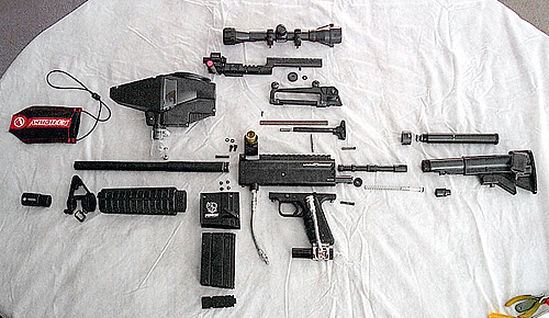 |
You should have something like what you see at left if you disassembled your entire marker (less the volumizer and valve body sections). |
Good luck, and remember, it is all about having fun.
